In the intricate world of metal manufacturing, precision and efficiency are vital. Two key techniques often utilized to ensure high-quality production are tabbing features and partial etching. These processes play a fundamental role in the overall manufacturing workflow, allowing for detailed and accurate production of metal parts.
Tabbing Features
Tabbing features are an essential part of the manufacturing process, particularly when working with larger sheets of metal. Typically, products are manufactured within a larger sheet and held in place by tabs. This method provides stability and ensures that the parts remain securely in place throughout the entire process. Once the manufacturing process is complete, the individual parts can be easily removed, or “de-tabbed,” from the larger sheet. This step is critical for further processing or packaging of the parts, ensuring they are ready for their next stage of production or shipment.
Partial Etching
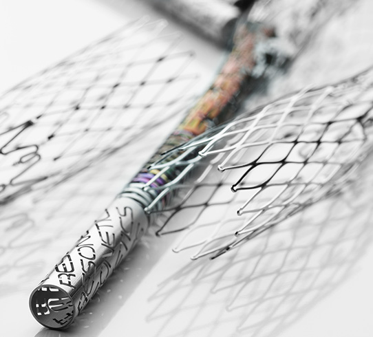
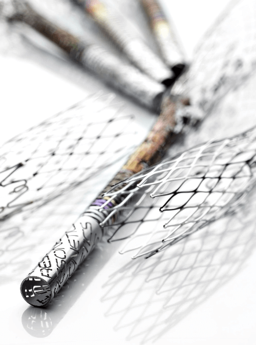
Partial depth etching is another common technique used in metal manufacturing. This process involves etching the metal to a partial depth in selected areas. Typical features created by partial etching are pockets, troughs, texture, letters/numbers for text, or for assisting in breaking off the parts during detab as described in the previous paragraph. Partial etch features can be nearly any depth, but 65% of material thickness is the most efficient for manufacturing. For instance, if the desired depth is approximately 65% of the metal thickness, single-side partial etched features can typically be etched simultaneously with double-side through-etched elements. This allows for precise control over the depth and dimensions of the etched areas.
Etching Tolerances and Substrate Dimensions
Precision is important in the etching processes, and understanding the tolerances and dimensions involved is crucial for achieving the desired results. Here’s a breakdown of the tolerances for through-etch and partial-etch processes, as well as the substrate dimensions typically used:
Through-Etch Tolerances
- Minimum Size: The through feature minimum size is equal to the material thickness plus 0.025 mm.
- Standard Tolerance: ± 15% of metal thickness.
- Critical Tolerance: ± 10% of metal thickness (±0.010 mm minimum).
- Center-to-Center Tolerance: ± 0.010 mm.
Partial-Etch Tolerances
- Thickness Reduction: Available for single or multiple areas and depths.
- Standard Reduction: 65% reduction in material thickness (0.025 mm minimum).
- Depth Tolerance: ± 10% of metal thickness removed (±0.004 mm minimum).
Substrate Dimensions
- Thickness Range: 0.015 mm to 0.500 mm.
- Standard Sheet Size: 12” x 27” (305 mm x 686 mm).
- Maximum Sheet Size: Capable of etching sheets up to 20” x 27” (508 mm x 686 mm).
These techniques not only ensure the precision and quality of the final products but also streamline the manufacturing workflow. By mastering these processes, manufacturers can achieve greater efficiency and produce high-quality metal parts that meet the stringent requirements of various industries.


